Architecture
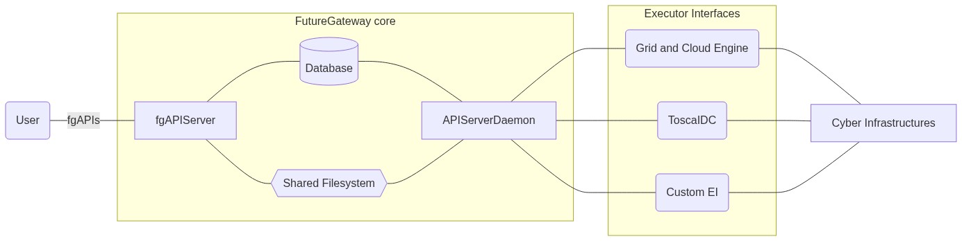
The core components of the FutureGateway Framework consists of its internal FutureGatway (FG) core that is responsible to handle user requests coming from REST APIs and executes the defined applications in the underlying DCIs. The core components are made of the following elements:
- Database - The FG database has an essential role and stores any information such as: Users, Groups, Roles, Applications, Tasks and even FG service configurations.
- API front-end - The API front-end receives user requests from the GUIs in the form of RESTful API calls. This part is only responsible to prepare an operation to execute on top of a given DCI.
- API server daemon - The daemon is the responsible of physically execute a task into a DCI, check its consistency and status, providing results to the final user as well. The daemon does not handles directly the application execution but it uses the Executor Interfaces. These elements, use the information coming from FG’ applications and infrastructures together with inputs coming from the APIs, then will execute the action in the proper DCI.
The following image provides a brief architecture overview:
Database
FG uses a relational database model and does not use any ORM system. This solution implies that FG can run only in the presence of a MySQL server. This is an explicit choice thought to offer to the FG adopters a transparent DB schema and easily recycle existing queries while developing new Executor Interfaces or while customising existing code.
The source code of each FG compoenent foresees an _db related section, collecting queries used by each specific software component. All queries are written in plain SQL query language; this also helps in customising code or write new software components.
The database and its schema, represents the core component of the whole FG. Any other part of the FG can be rewritten using any kind of language and/or software technology just interacting with it.
One key element of the database schema is represented by the queue table, named ‘as_queue’ (API Server queue). This table is also a simplified solution to provide a relying queue system among one or more front-ends and underlying api-servers (see the architecture figure above).
Front-end
The front-end component of the FG is only responsible to satisfy the FG API specifications. The fgAPIServer is just a lightweight implementation written in Python and exploiting the Flask micro-framework to easily implement the FG RESTful API calls.
The figure below, explains the API handling work-flow processed by the API front-end component. In the first stage the incoming REST call, authentication and authorization will be checked, then the requested command will be prepared and eventually data will be updated in the database. In case of DCI operations, these will be registered in the _queue table__ and finally the response will be provided back to the user. Input and output streams are ALL in json format except for the files endpoint that is used to donwload files.
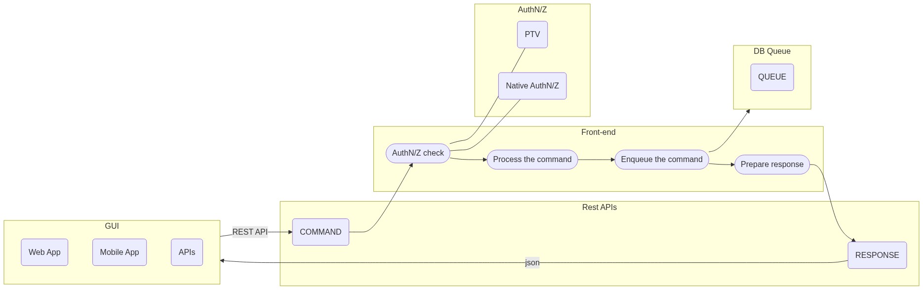
The PTV service in the figure, has been introduced to isolate the FG from the external portal authentication system. The PTV consists of a REST end-poin with few available calls. The PTV based authentication/authorization method, was the only available in the earlier phases of the FG, while actually it is suggested to interface directly the FG membership directly from the web interface.
API Server
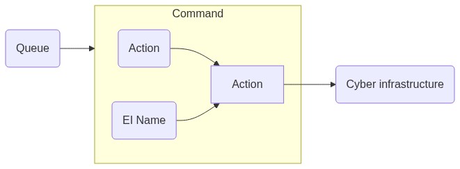
The APIServer component has the responsability to physically execute applications on top of the configured infrastructures. The APIServerDaemon is a Java implementation specifically written to support the Grid and Cloud Engine component capable to target many DCIs thanks to the adoption of the JSAGA libraries. The figure below describes the workflow of the API Server, at the beginning a polling thread extracts a record from the queue_table. Each record has two important elements describing the action to perform on the DCI end the corresponding Executor Interface (EI). The EI information will be used to identify the correct DCI handler, this will use the action information together with the Application and the related Infrastructure configuration, to perform the requested activity on top of the the DCI.
Executor Interface
Executor Interfaces are modular software components having the final responsability to physically perform the given activity into the DCI. By design the API Server should instantiate dinamically EIs, starting from the name registered in the queue_table, however this is not happening in the current version of the APIServerDaemon, where an internal if ... else if ... else <unknown EI> chain statically handles the supported EIs.